
Laminate data sheet
RO4350B
8 parameters from the manufacturer data sheet. Values are for reference; the confirmed specification governs.
Properties
| Property | Value | Unit | Direction | Condition | Test method |
|---|---|---|---|---|---|
| Dielectric Constant, εProcess | 3.48±0.05 | -- | Z | 10 GHz/23℃ | IPC-TM-650 2.5.5.5 |
| Dissipation Factor, tanδ | 0.0037 | -- | Z | 10 GHz/23℃ | IPC-TM-650 2.5.5.5 |
| Tg | >280 | °C TMA | -- | A | IPC-TM-650 2.4.24.3 |
| CTE (x) | 10 | ppm/℃ | X | -55℃ to 288℃ | IPC-TM-650 2.4.41 |
| CTE (y) | 12 | ppm/℃ | Y | -55℃ to 288℃ | IPC-TM-650 2.4.41 |
| CTE (z) | 32 | ppm/℃ | Z | -55℃ to 288℃ | IPC-TM-650 2.4.41 |
| Copper Peel Strength | 0.88 (5.0) | N/mm (pli) | -- | after solder float 1 oz. | IPC-TM-650 2.4.8 |
| Lead-Free Process Compatible | Yes | -- | -- | -- | -- |
Boards built on this laminate
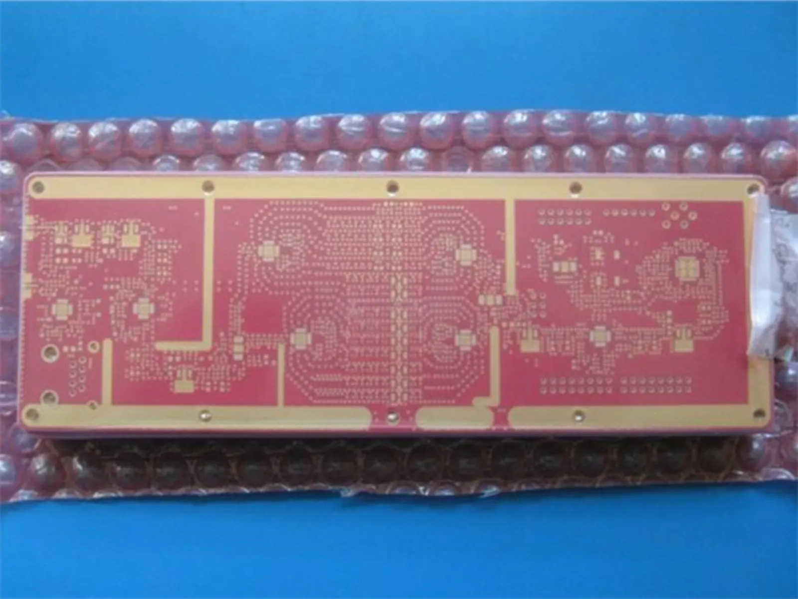 Hybrid 10-Layer PCB RO4350B 6.6mil + FR-4 with Red Solder Mask and Immersion Gold
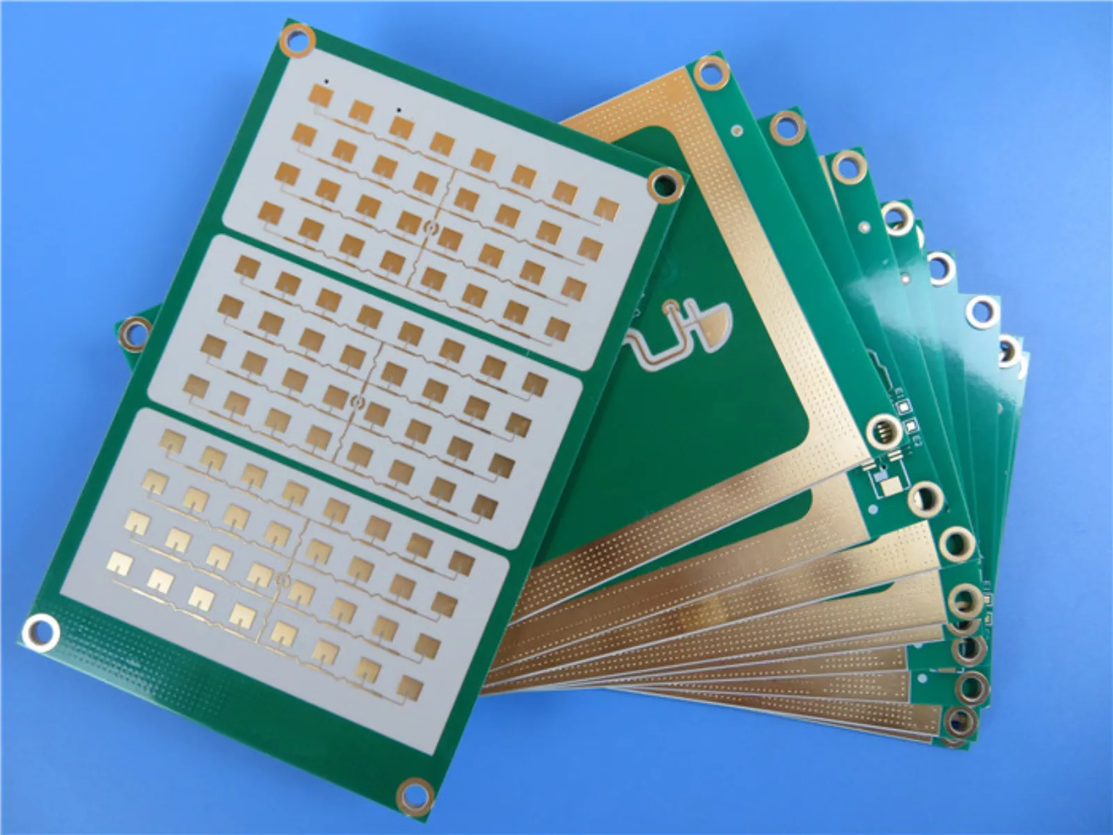 Hybrid High Frequency Printed Circuit Boards 3-Layer Hybrid RF PCB Made On 13.3mil RO4350B and 31mil RT/Duroid 5880
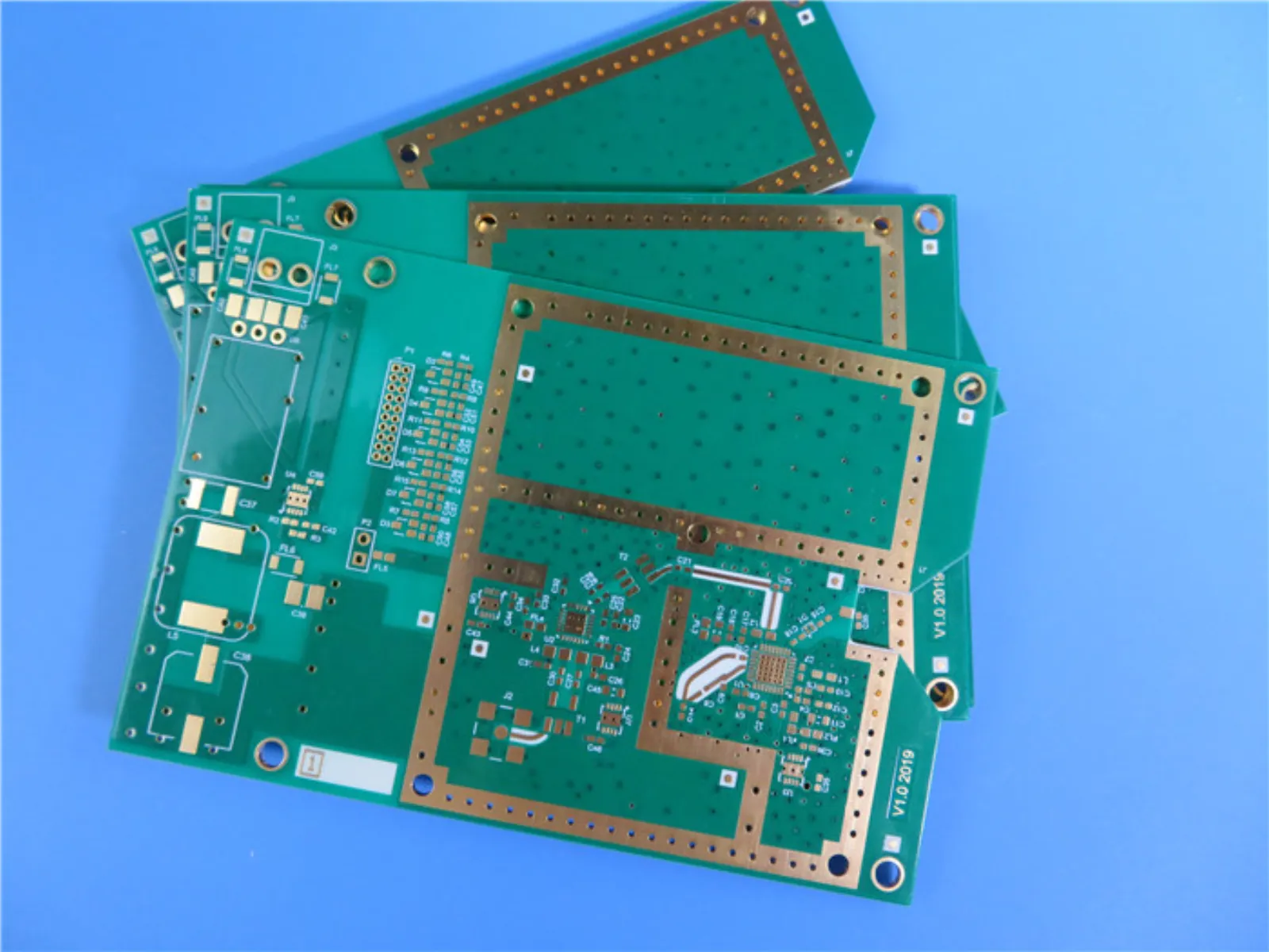 Hybrid PCB | Mixed Material 4-Layer PCB Made On 20 mil RO4350B + FR4 With Blind Via
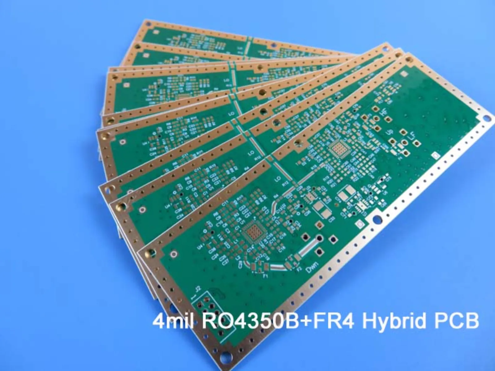 Hybrid PCB on Rogers RO4350B and High Tg FR-4 4-Layer Mixed PCB on 4mil RO4350B and 0.3mm FR-4
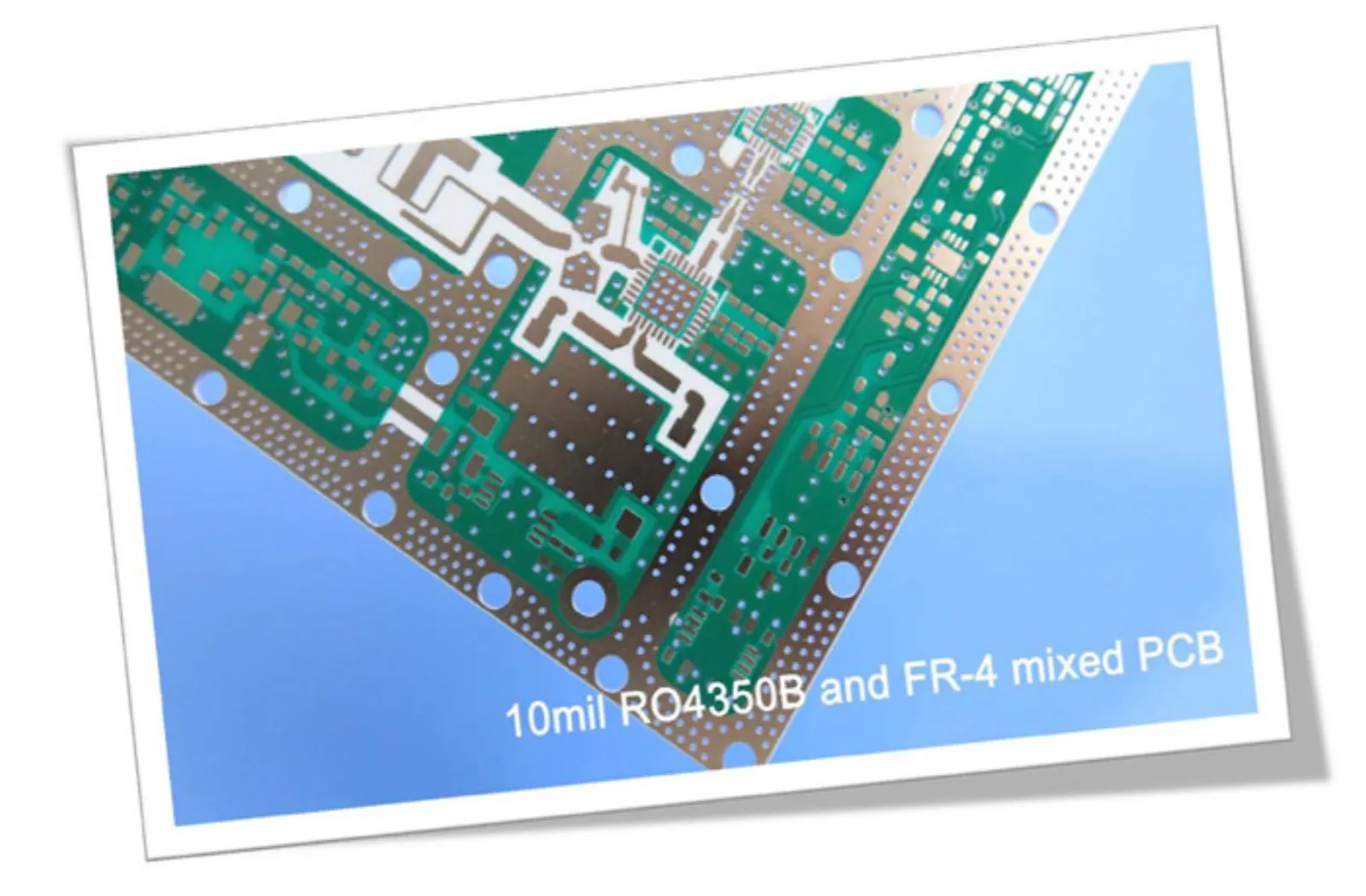 Hybrid PCB | Mixed Material PCB Built on 10 mil RO4350B + FR-4 with Depth Controlled Drill
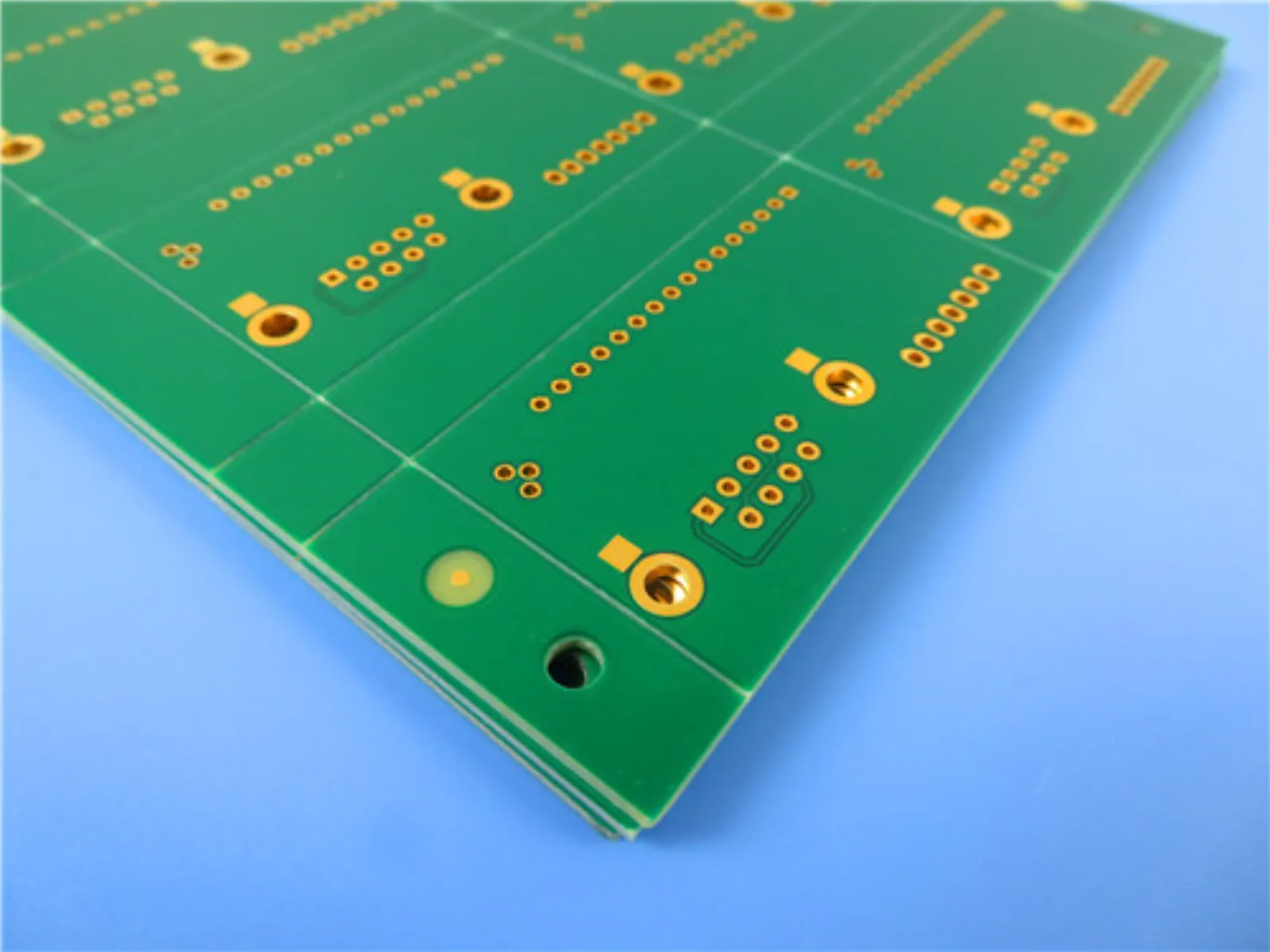 High-Performance 4-Layer Hybrid PCBs with RO4350B and S1000-2M for Advanced RF Applications
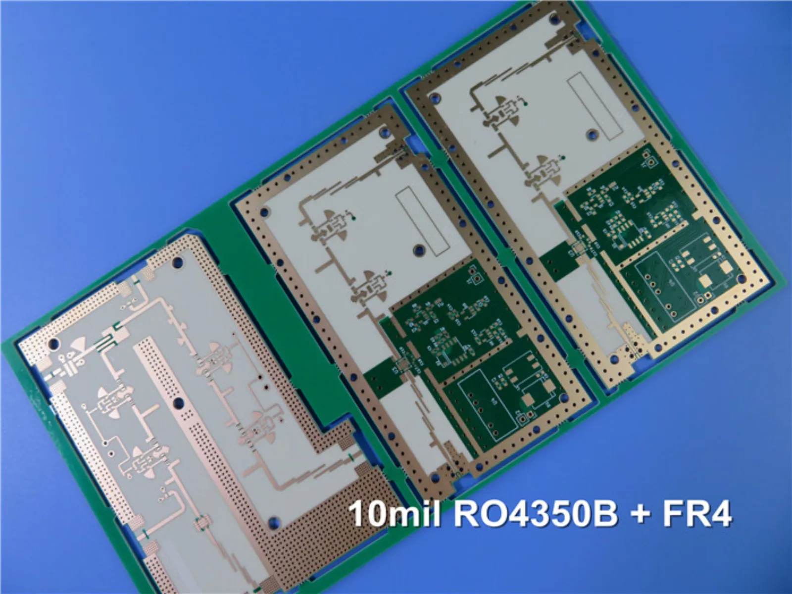 Hybrid RF Circuit Board 5-Layer High Frequency PCB Built on 10mil RO4350B and FR-4
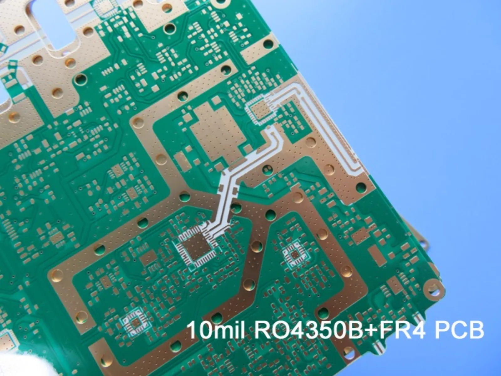 Hybrid RF High Frequency 6-Layer PCB Built on 10mil (0.254mm) RO4350B and FR-4 with Blind Via
- Hybrid Rogers RO3003 6-Layer RF PCB Bonded by FastRise 28 Prepreg for High Speed Signal Transmission
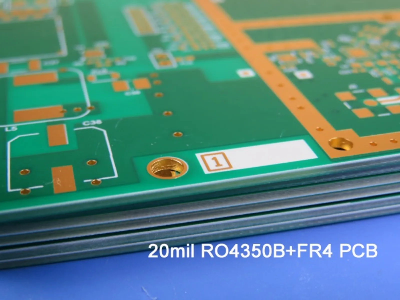 Hybrid High Frequency PCB 6-Layer Mixed PCB on 20mil RO4350B and FR-4 with Blind Via
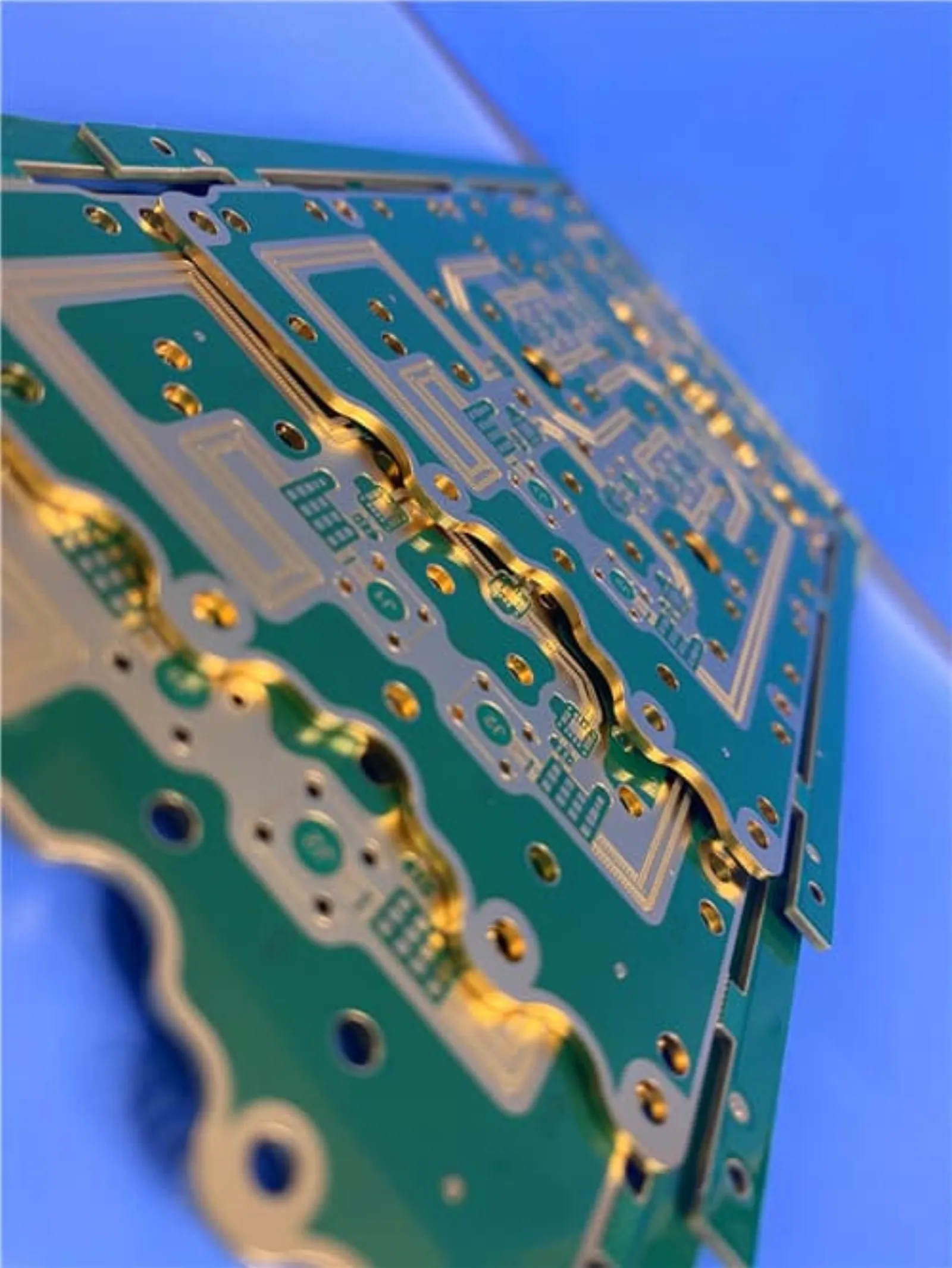 6-Layer Hybrid RO4350B + IT180 PCB with Blind Via & ENIG Finish for Telecom and Microwave Applications
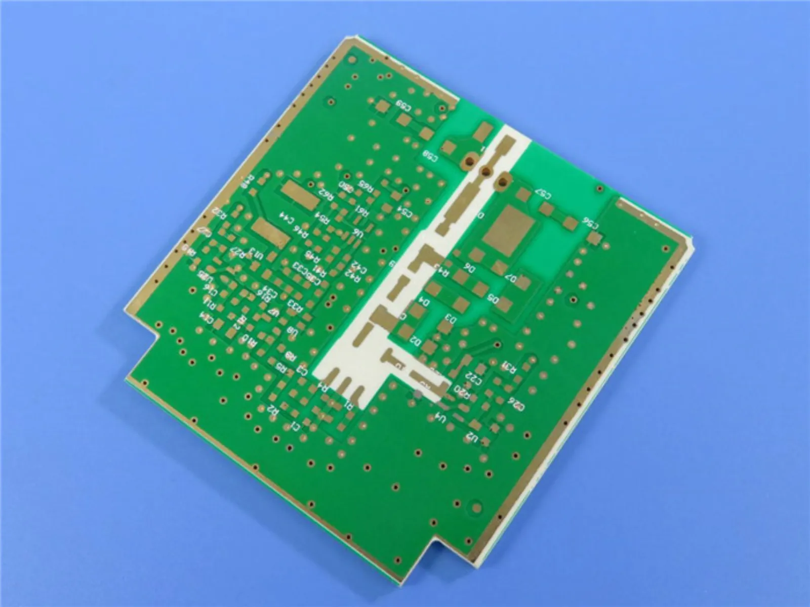 Hybrid PCB Mixed Material Circuit Board Different Materials Combined PCB RO4350B + FR4 + RT/duroid 5880 with Immersion Gold
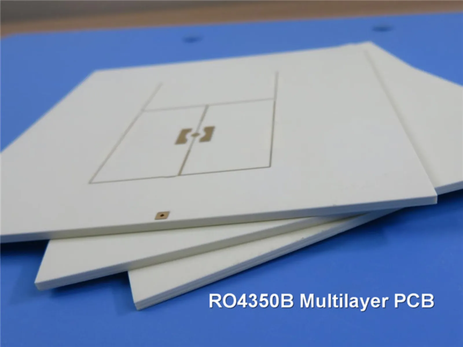 10 Layer High Frequency PCB Built on 5 Cores of 10mil RO4350B with 4mil RO4450F for Broadband Wireless Solutions
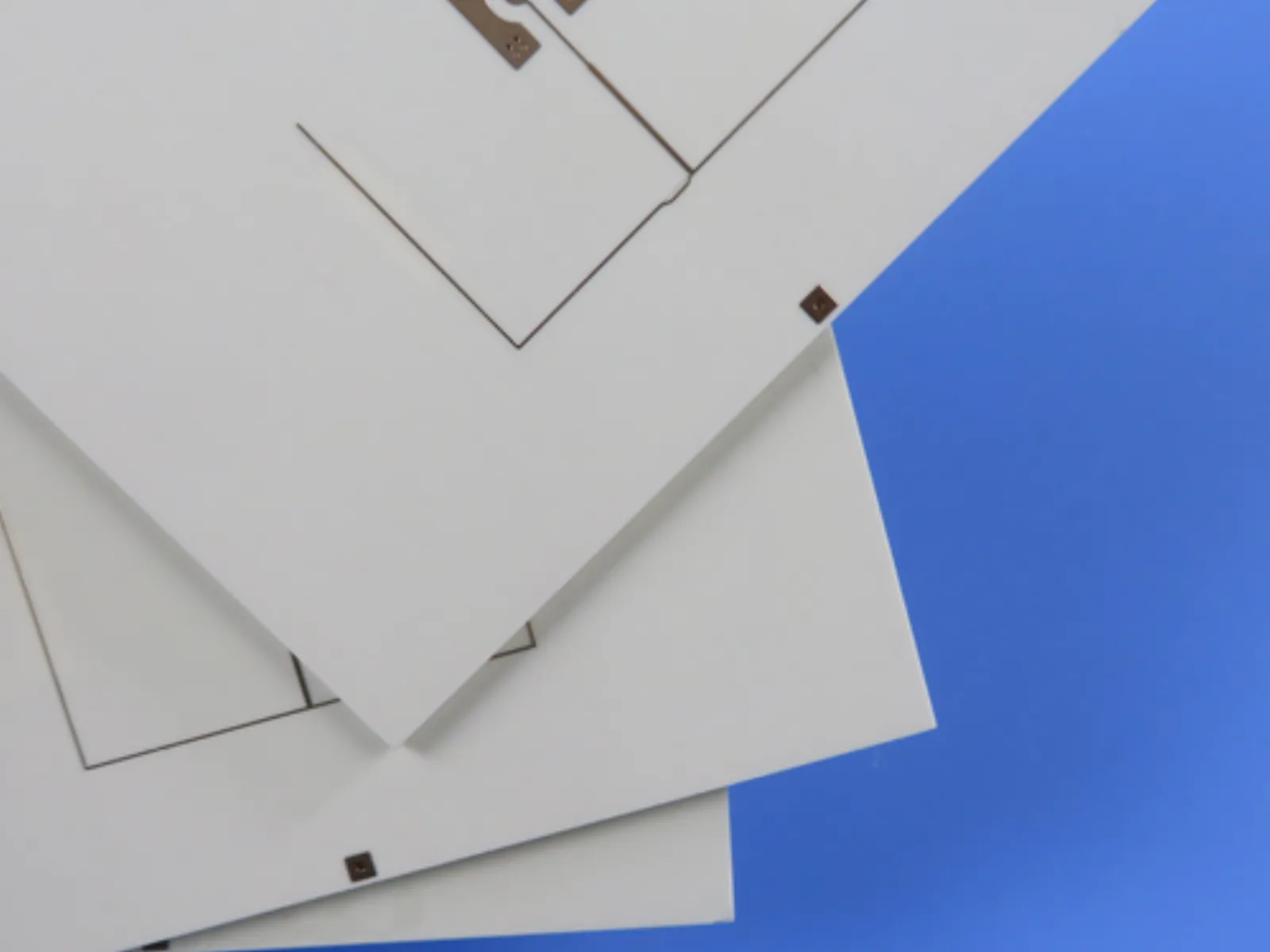 18-Layer RO4350B High-Frequency PCB | 3.2mm Thick | ENIG + Selective Hard Gold Finish
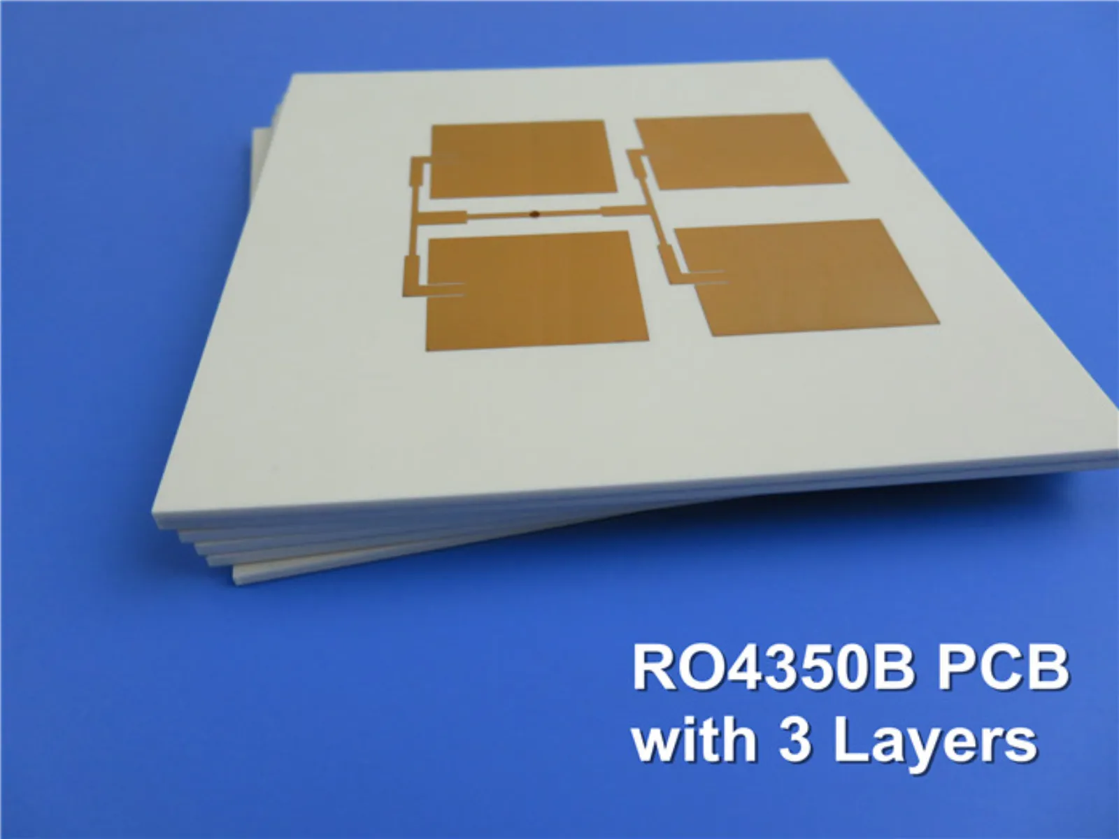 3-Layer High Frequency PCB Built on 60mil RO4350B and 6.6mil RO4350B with ENIG for Wireless Boosters
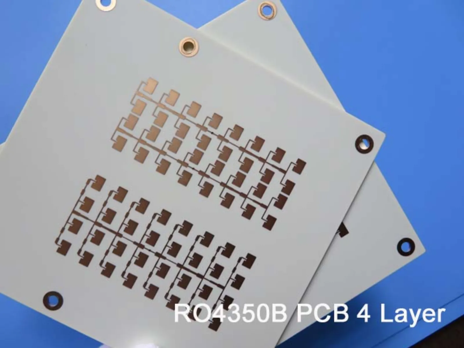 4-Layer High Frequency PCB on 6.6 Mil RO4350B and 10 Mil RO4350B for Radar Systems
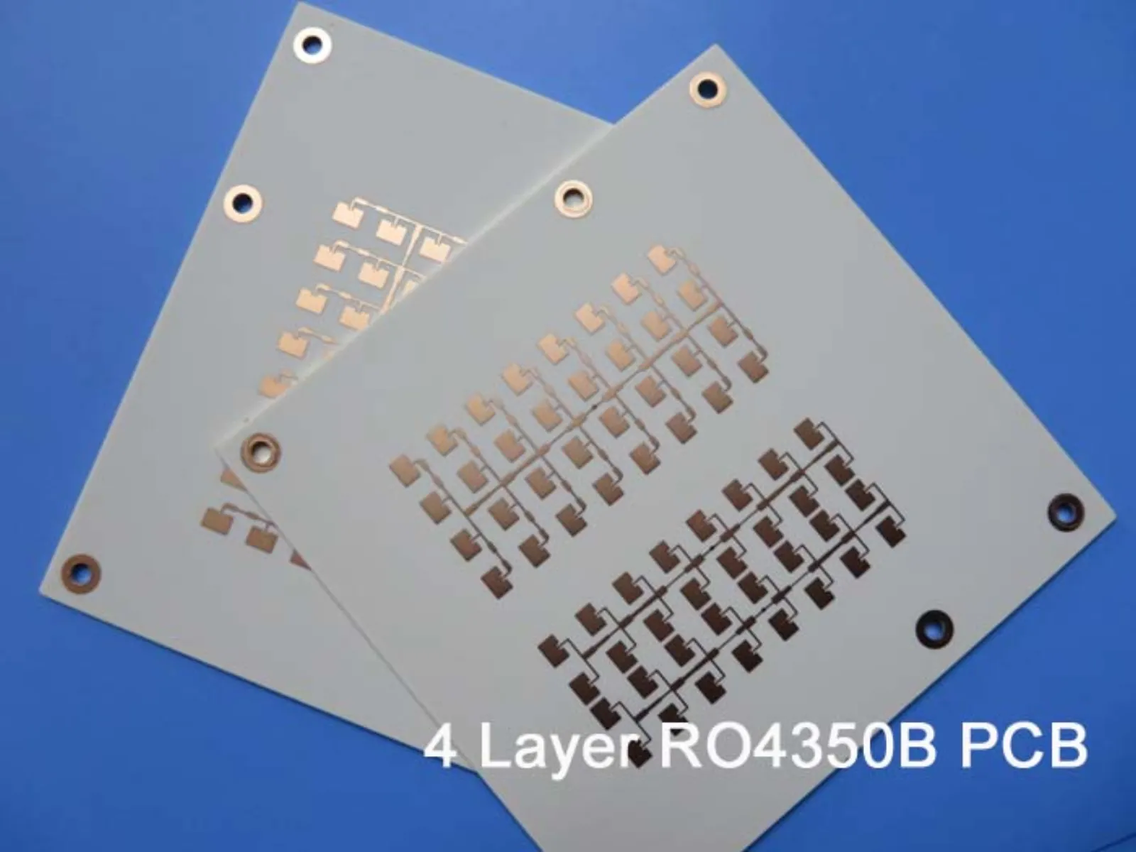 4 Layer RF Circuit Board on Rogers 60mil RO4350B and 10mil RO4350B with Back Drill for UHF Coupler
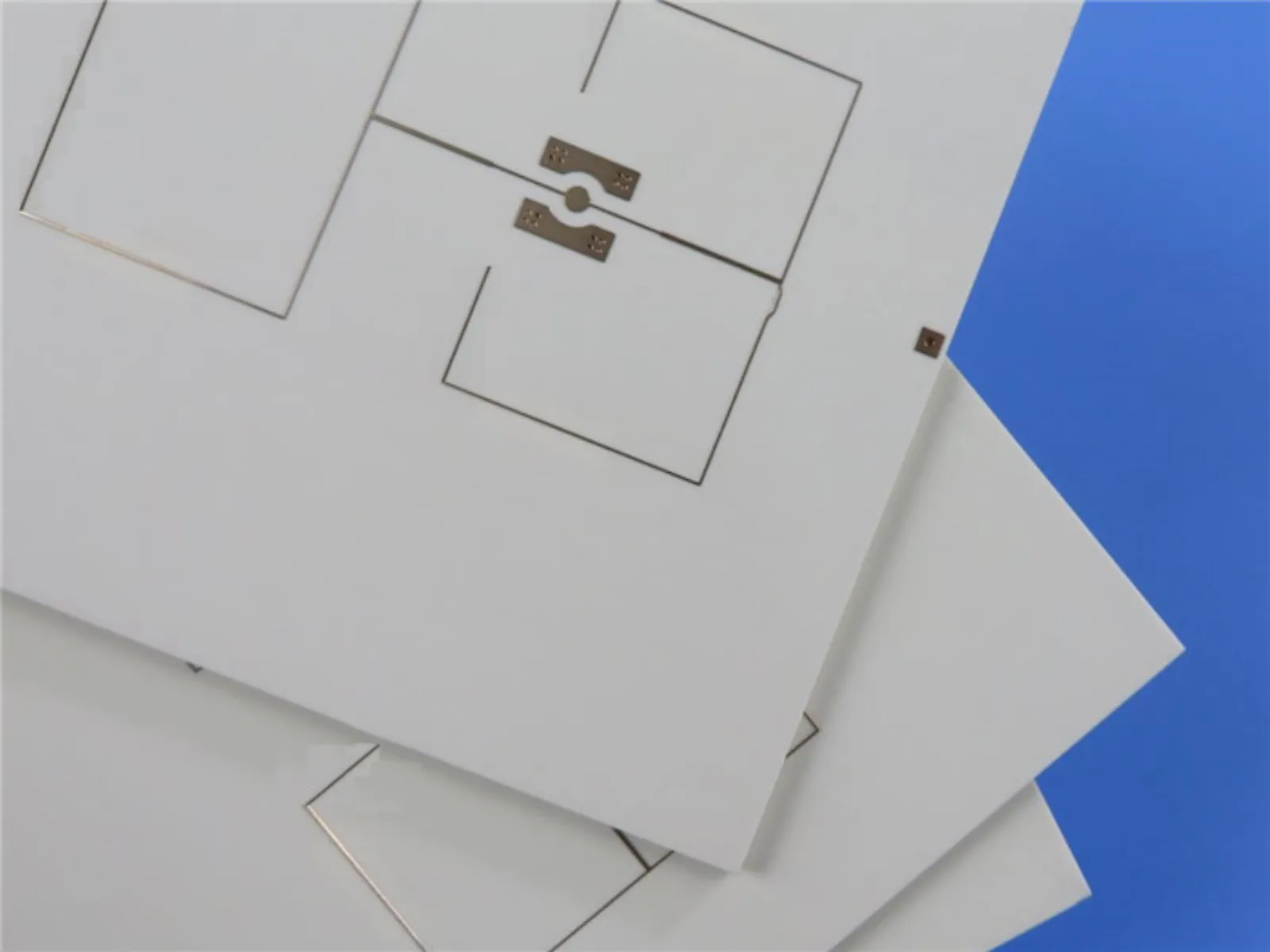 4 Layer High Frequency PCB Built on Dual 20mil RO4350B Cores with Back Drill for GPS Trackers
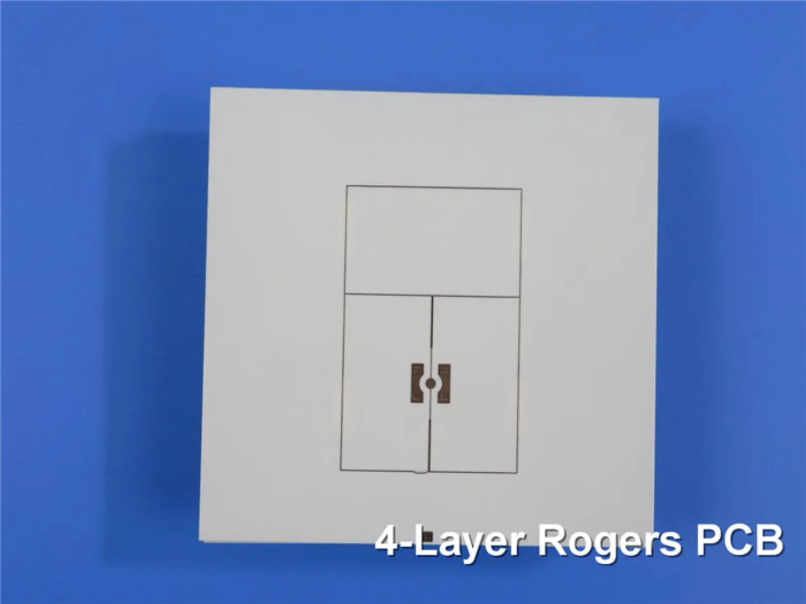 4 Layer High Frequency PCB Built On 6.6mil and 20mil RO4350B with Blind Via for Radar Sensor
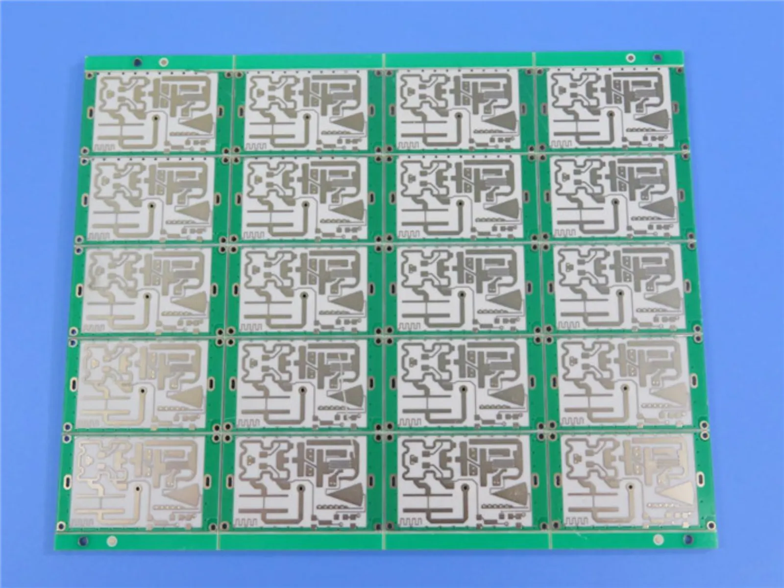 4 Layer High Frequency PCB on Dual 10mil RO4350B Cores for Wireless Antenna Systems
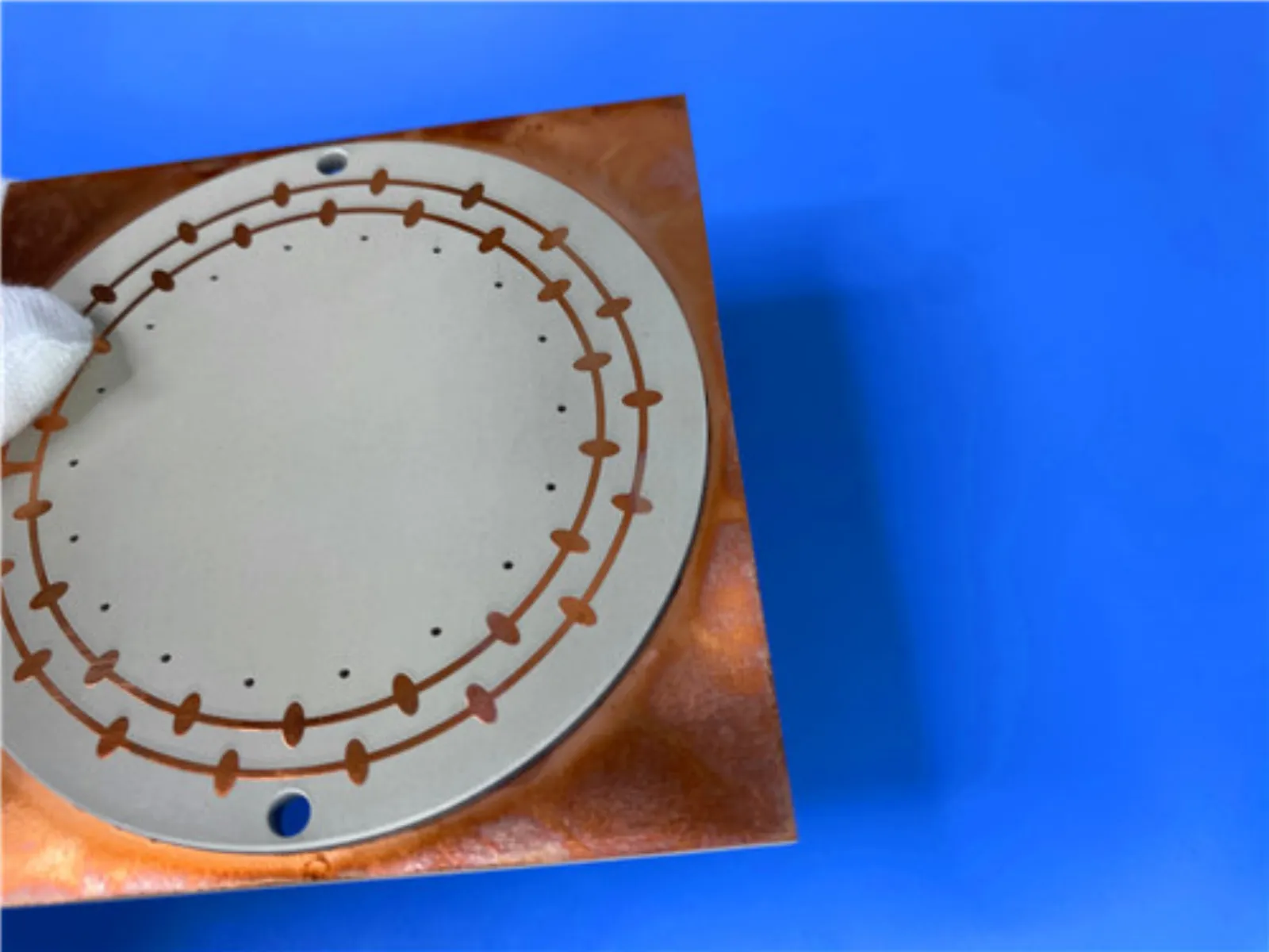 High-Performance 4-Layer HDI PCB Using RO4350B Material
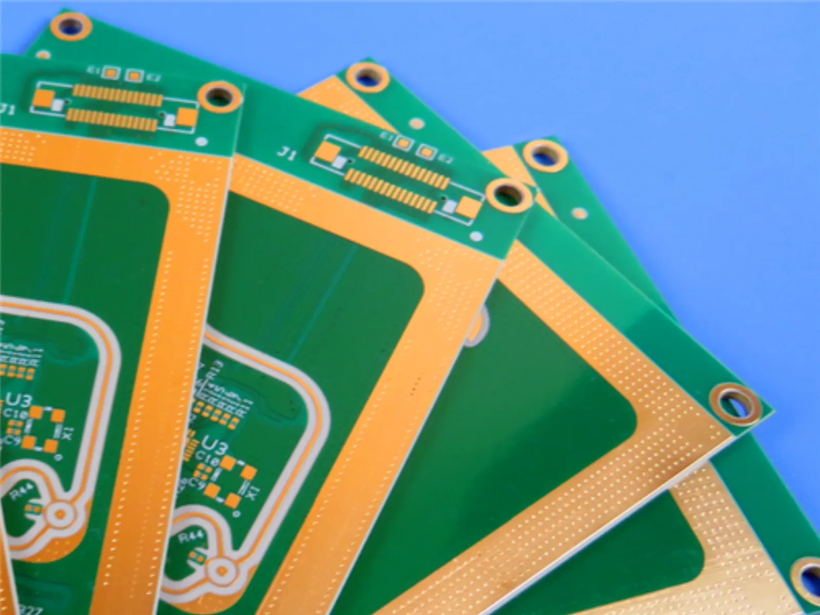 8-Layer HDI RF PCB RO4350B 1.6mm ENEPIG Finish Impedance Controlled
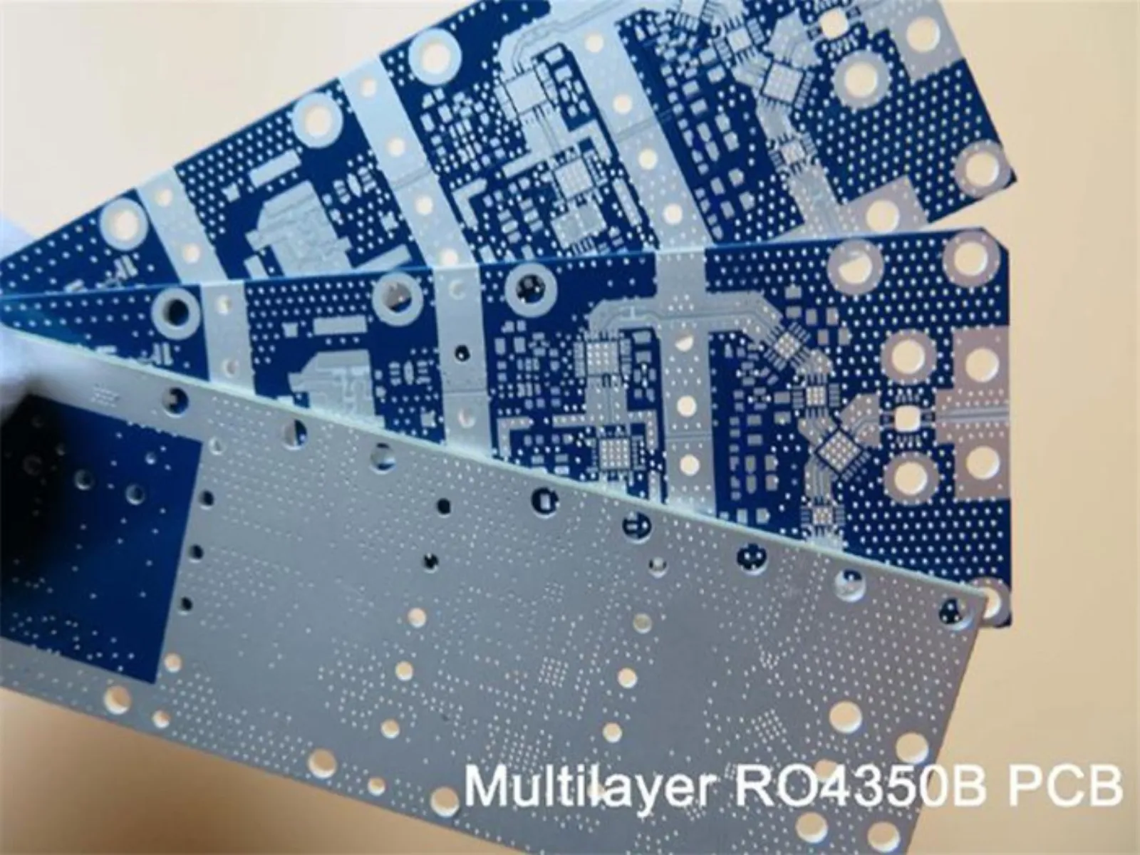 Rogers RO4350B High Frequency Printed Circuit Board with 10mil, 20mil, 30mil and 60mil thick Coating with Immersion Gold
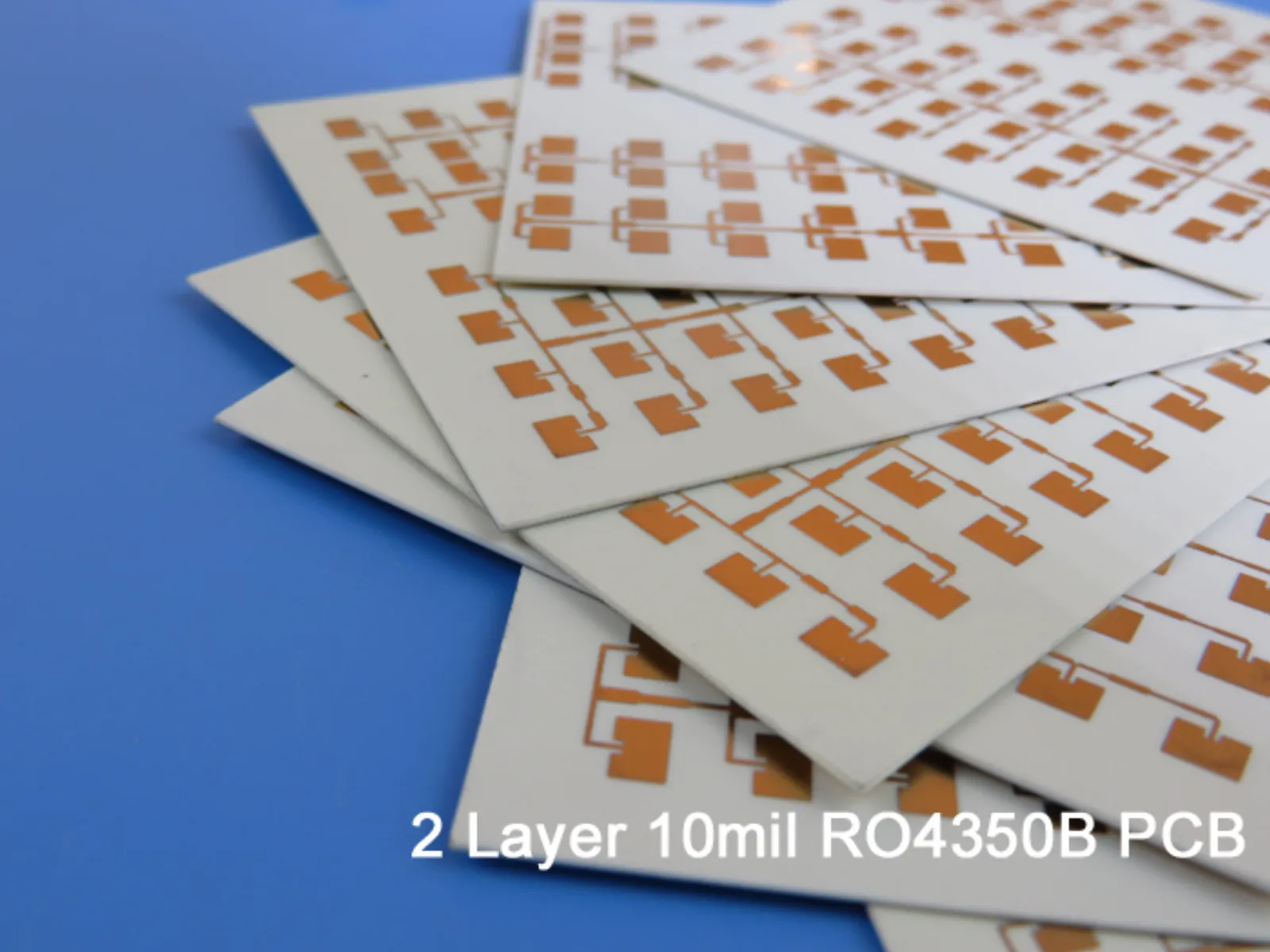 High-Frequency PCB: RO4350B 10mil (0.254mm) Double-Sided RF PCB for LTE Applications
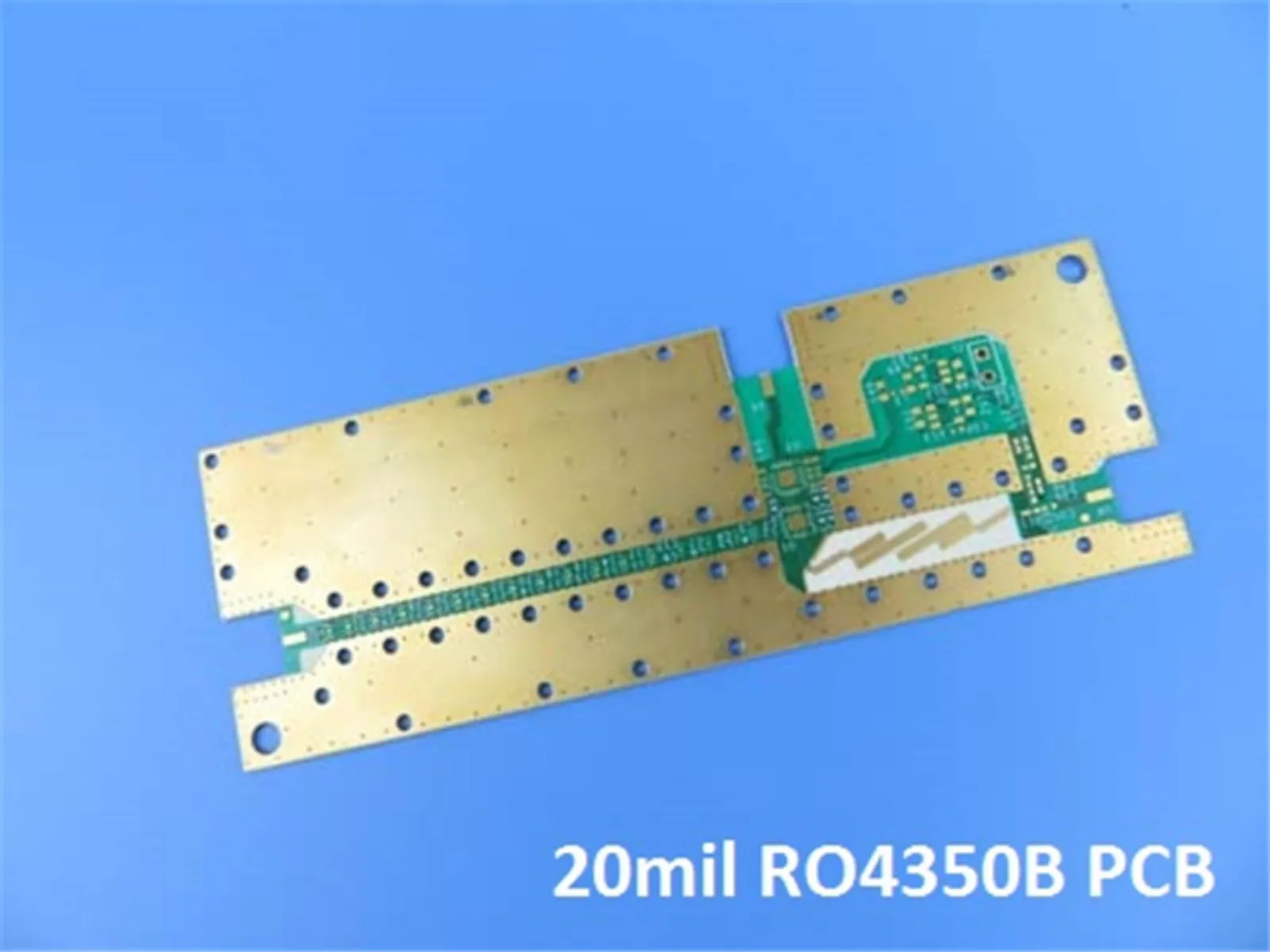 High Frequency PCB Rogers RO4350B 20mil 0.508mm Double Sided RF PCB for Splitter
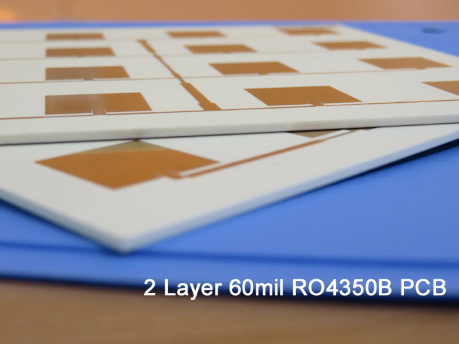 High Frequency PCB: Rogers 60mil 1.524mm RO4350B Double-Sided RF Circuit Board for Patch Antenna
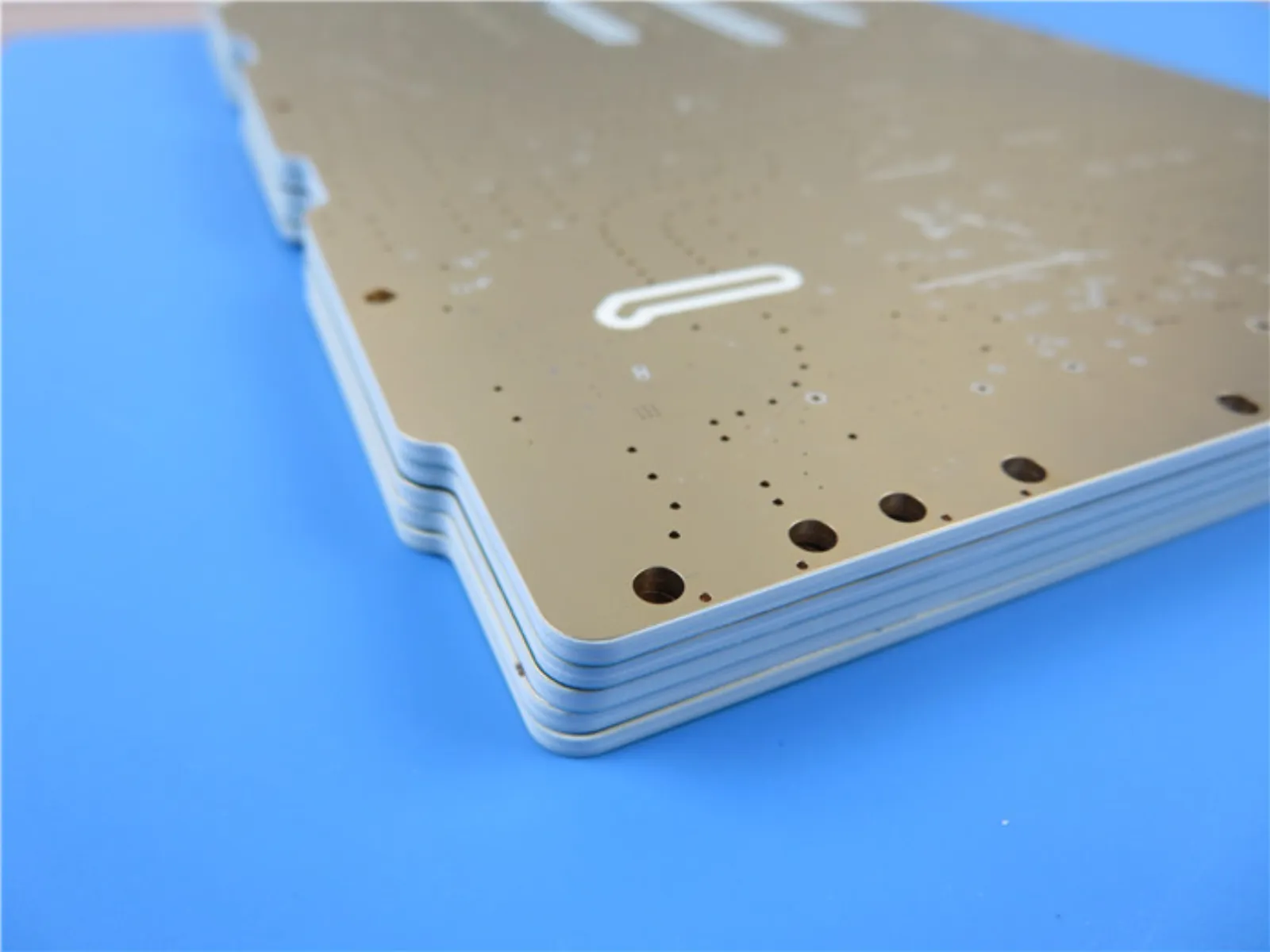 RO4350B LoPro RF PCB Rogers 60.7mil Reverse Treated Foil PCB Circuit Board With Immersion Gold
Need a quote for this laminate?
Send us your Gerber, layer count and quantity — you get a DFM note and an indicative price within 4 working hours.
Get a quote