电路板丝印标注推荐尺寸、调整原则与方法详解
发布于 2025-03-06
Adjustment of Silkscreen Markings
For later component assembly, especially for manual assembly, a PCB assembly diagram is generally produced to facilitate component placement and positioning. At this point, the necessity of silkscreen markings becomes evident.
During production, silkscreen markings on the PCB can be displayed or hidden, but this does not affect the output of the assembly diagram. By pressing the shortcut key “L” to close all layers, you can then individually select to open only the silkscreen layer and the corresponding solder mask layer to adjust the markings.
Principles and Recommended Sizes for Adjusting Silkscreen Markings
The following are the principles and commonly recommended sizes for adjusting silkscreen markings:
1.Silkscreen markings should not overlap with the solder mask to avoid missing markings after production.
2.Silkscreen markings should be clear, with recommended font sizes of 4/25 mil, 5/30 mil, and 6/45 mil for width/height.B
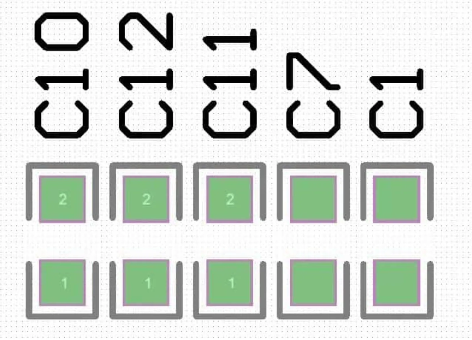
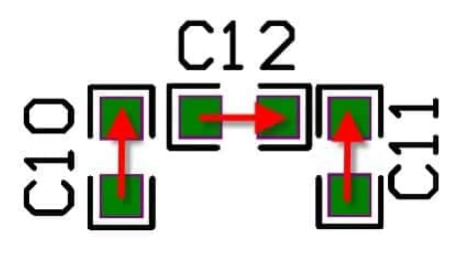
3.Maintain uniformity in orientation; generally, a PCB should not have more than two orientations. It is recommended that letters are positioned to the left or below, as shown in Figure 11-21.
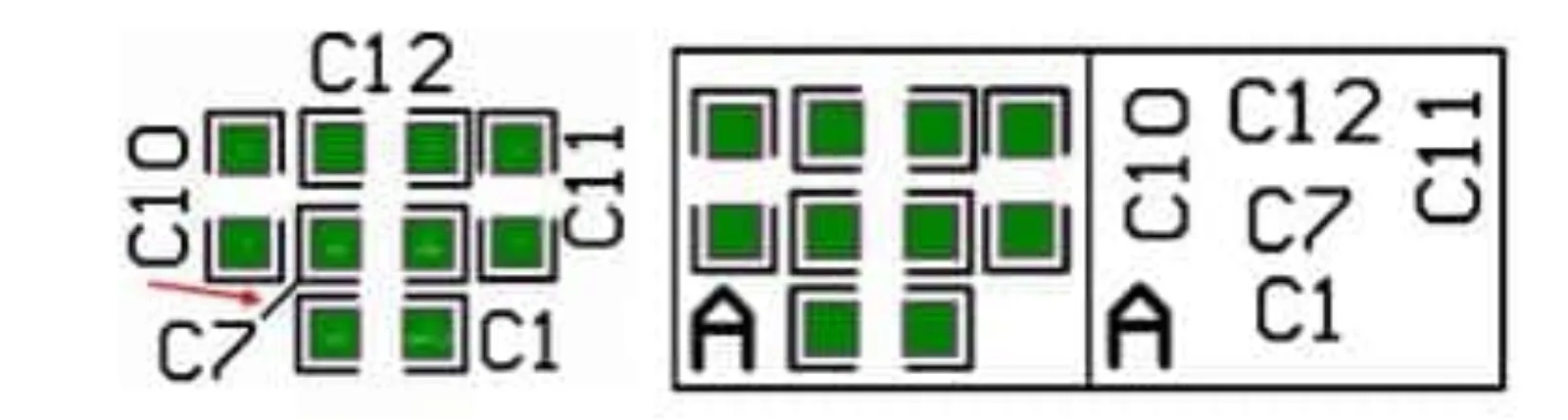
4.For some arranged silkscreen identifiers, you can use 2D auxiliary lines or boxes for marking to facilitate reading, as shown in Figure 11-22.
Methods for Adjusting Silkscreen Markings
Altium Designer offers a quick method for adjusting silkscreen markings through the "Component Text Position" function, allowing for the placement of component markings around the component or at its center.
1.Select the component that needs adjustment.
2.Press the shortcut key “AP” to enter the "Component Text Position" dialog, as shown in Figure 11-23. This dialog provides two placement options: "Identifier" and "Comment." Here, we will explain using "Identifier" as an example.
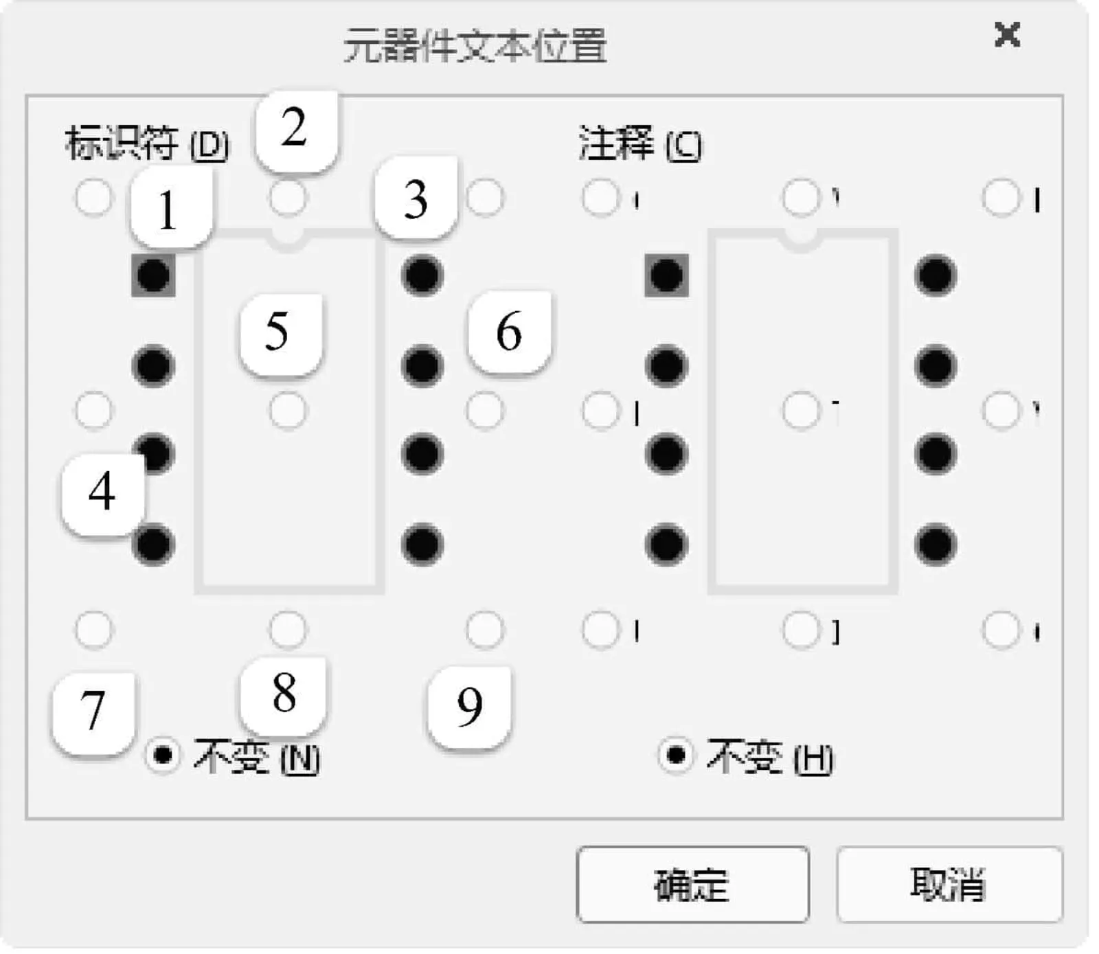
3.The "Identifier" offers several directional placements: up, down, left, right, top left, bottom left, top right, and bottom right, which can correspond to the numeric keys on the numeric keypad. To quickly place the silkscreen marking above the selected component, press the numeric keys “5” and “2” on the numeric keypad, as shown in Figure 11-24. Other directional placements are similar; for instance, pressing “5” and “6” places it to the right of the component, and “5” and “8” places it below the component.